A circuit diagram is a topology drawing, not a picture — distance on the page means nothing and only connection means anything. This is how to read one in order, what the letters beside each symbol are doing, and which of the two symbol standards you are actually being held to.
Quick answer
Start at the source and follow the line. Components you pass without ever choosing a branch are in series; a split that rejoins is parallel. Beside each symbol, the letter is the class and the number is which one — R1 is the first resistor, U1 the first integrated circuit. A dot at a crossing means connected; no dot means the wires only cross. And the resistor is a zigzag in the American tradition (IEEE/ANSI 315) but a plain rectangle in the international one (IEC 60617).
What a circuit diagram is, and how it differs from a wiring diagram
A circuit diagram states which components exist and what each one is connected to. That is the whole of its content. Where a component sits on the page, how long a wire is drawn, whether the layout is square or sprawling — none of it carries meaning. Two diagrams that look nothing alike can be the same circuit, and a diagram that looks tidy can describe a circuit that does not work.
Three drawings get confused with each other, and the difference is what each one refuses to tell you.
A schematic, which is what people mean by circuit diagram, shows electrical connection with standard symbols and arranges them for readability. It does not tell you where anything physically goes. A wiring diagram shows the actual conductors, terminals and connector pinouts, and position matters because someone is going to follow it with a crimping tool. A pictorial diagram draws the parts as they look, which makes it obvious to a beginner and useless for anything dense.
The reason to be strict about this is that the symbols are not a convention that grew up informally. They are standardised, and the committee that maintains them says why: internationally standardised graphical symbols contribute to the effective and efficient preparation of documentation for products and installations, and to the enhanced understanding of those documents. A symbol is a promise that the same shape means the same thing to a reader who does not share your language.
The symbols you need to read almost any circuit diagram
The international symbol set is IEC 60617, maintained as a database rather than a printed document — it was the first IEC standard converted into database form. The database currently holds some 1900 symbols, each with a reference number, a title in English and French, and a graphical representation in GIF, with some available as vectorised EPS. It describes itself, unambiguously, as the official source of IEC 60617.
Nobody needs 1900 symbols to read a diagram. Roughly a dozen cover almost everything you will meet outside a specialist field.
| Component | What the symbol looks like | What it does |
|---|---|---|
| Battery or cell | Alternating long and short parallel bars; the long bar is positive | Supplies the voltage the rest of the circuit works against |
| Resistor | A zigzag (American tradition) or a plain rectangle (international) | Limits current; sets voltages by division |
| Capacitor | Two parallel plates with a gap | Stores charge; blocks steady current, passes changing current |
| Polarised capacitor | One straight plate, one curved plate, with a + mark | Same, but must be wired the right way round |
| Diode | A filled triangle pointing at a bar | Conducts triangle to bar only |
| LED | A diode with two small arrows leaving it | Conducts one way and emits light while it does |
| Switch | A hinged line between two small open circles | Breaks the path when open |
| Push button | A switch with a plunger drawn above the contacts | Closes only while it is held |
| Lamp | A circle with a cross through it | Turns current into light and heat |
| Inductor | A row of loops or humps on a line | Stores energy in a magnetic field; opposes change in current |
| Ground | A stack of horizontal bars, each shorter than the last | The reference point every voltage is measured against |
| NPN transistor | A vertical base bar with two angled leads, one carrying an arrow outward | Uses a small base current to control a much larger one |
| Integrated circuit | A plain rectangle with numbered pins and a part number inside | Whatever the datasheet says it does |
That table describes the shapes rather than reproducing them, and the reason is worth stating plainly: neither standards body publishes its normative drawings free. IEC 60617 is a subscription database, renewing at CHF 280 a year, and the American standard is a purchase. If you need the authoritative artwork for a specific symbol — the exact proportions, the connection points on the modular grid IEEE 315 specifies — that is where it lives, and a reference chart of unknown provenance is not a substitute.
One caveat on the count. The IEC webstore record for IEC 60617:2026 DB says the database contains more than 1500 symbols, while the database's own home page says some 1900. We have used the higher figure because it comes from the page that calls itself the official source, but the two IEC pages disagree and it is better to say so than to pick one silently.
Why the resistor looks different in American and European diagrams
This is the single most common source of confusion for anyone reading across traditions, and the answer is that there are two standards, with two very different lifecycles.
IEC 60617 is alive. It is maintained by IEC technical committee 3, revised continuously because it is a database rather than a printed book, and its current release, IEC 60617:2026 DB, was published on 4 March 2026. National committees maintain localised versions in Finnish, Japanese, Danish and Chinese.
IEEE/ANSI 315-1975 is not. The full title is IEEE Standard for Graphic Symbols for Electrical and Electronics Diagrams (Including Reference Designation Letters), it was approved by the IEEE standards board on 4 September 1975 and by ANSI on 31 October 1975, published on 29 December 1975, and reaffirmed once, on 2 December 1993. On 7 November 2019 it was moved to Inactive-Reserved status. The symbols in every American schematic drawn this year trace back to a document last revised fifty-one years ago and withdrawn from active status seven years ago.
| IEC 60617 | IEEE/ANSI 315 | |
|---|---|---|
| Current release | IEC 60617:2026 DB, 4 March 2026 | 315-1975 |
| Status | Published, maintained continuously | Inactive-Reserved since 7 November 2019 |
| Last reaffirmed | Not applicable — database maintenance | 2 December 1993 |
| Form | Subscription database, ~1900 symbols | Purchased document |
| Resistor drawn as | Plain rectangle | Zigzag |
| Maintained by | IEC technical committee 3 | IEEE SA Standards Board |
The practical upshot: a resistor drawn as a zigzag and a resistor drawn as a rectangle are the same component, and neither is wrong. What decides which you should draw is the audience or the standard you are held to, not which one you learned first. The resistor is the divergence people notice, but it is not the only one, and the only reliable way to settle a specific symbol is the document itself rather than a reference chart of unknown provenance.
It is worth knowing that convergence was the intention from the start. The abstract of IEEE 315-1975 records that a substantial effort was made to make the standard compatible with the approved IEC recommendations of the day. The two traditions were never meant to be rivals; one of them simply stopped being revised.
What the letters and numbers beside each symbol mean
A symbol says what kind of component it is. The label beside it says which one, and what it is.
That label is a reference designator, and it has a fixed anatomy: a letter
for the class, a number for the instance, and usually the value after it. In
R1 220Ω, R means resistor, 1 means it is the first one on this diagram,
and 220Ω is what to buy. Once you know the letters, a diagram you have never
seen becomes readable in the order the designators run.
| Letter | Class | Reads as |
|---|---|---|
| R | Resistor | R1, R2 — value in Ω, kΩ, MΩ |
| C | Capacitor | C1 — value in pF, nF, µF |
| L | Inductor | L1 — value in µH, mH |
| D | Diode | D1 — part number, or just LED |
| Q | Transistor | Q1 — part number, e.g. 2N3904 |
| U | Integrated circuit | U1 — part number, e.g. 555 |
| S | Switch | S1 — no value; the symbol carries the type |
| K | Relay | K1 — coil voltage |
| T | Transformer | T1 — turns ratio or secondary voltage |
| F | Fuse | F1 — rating in A |
Both standards define these letters normatively, and the full class lists are inside the paid documents rather than in this table. IEEE 315 carries them in the American tradition — the words are right there in its title — and internationally the job belongs to IEC 81346-2:2019, a 197-page horizontal standard that establishes classification schemes with defined object classes and their associated letter codes, intended for use in reference designations.
The 2019 edition made a change worth knowing about even if you never open it. Its entry classes are defined to reflect the inherent function of the object being classified, rather than what the object physically is. A third edition is in preparation, forecast for September 2026.
The difference between a designator and a description shows up immediately when you put two versions of the same diagram side by side.
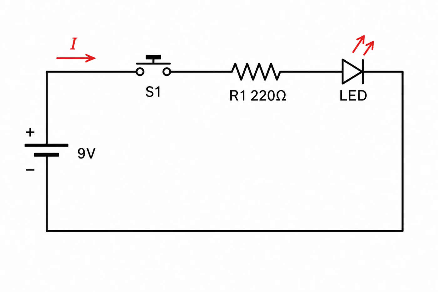
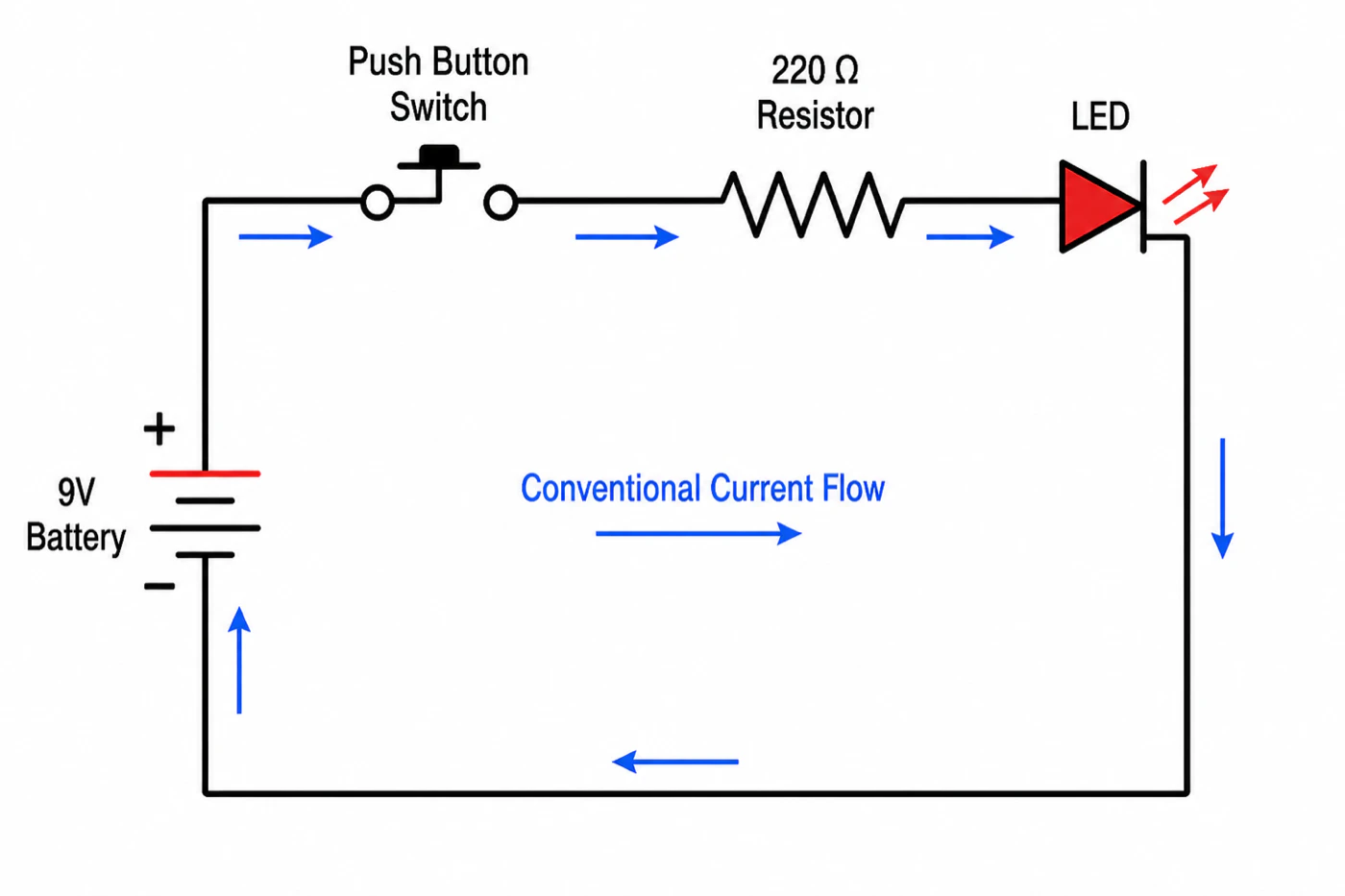
The second version is friendlier and does not scale. Designators exist so that the diagram, the parts list, the board and the prose in your paper can all point at the same object. A method section that says the 220 Ω resistor becomes ambiguous the moment a second one appears; one that says R1 never does.
How to tell a series circuit from a parallel one on the page
Trace it. This is a reading procedure, not a formula.
Put a finger on one terminal of the source and follow the line. If you reach the other terminal without ever having to choose between two paths, everything you passed is in series. The same current flows through all of it, and the voltages across the components add up to the supply voltage. Where the line splits at a junction and the branches meet again at another junction, those branches are in parallel. Each branch sees the same voltage, and their currents add up to the current arriving at the junction.
Two things make this harder than it should be on real diagrams.
The dots are load-bearing. A filled dot where lines meet means the conductors are connected there. Lines that cross with no dot are not connected; they only pass over one another on the page. Since a dropped dot and a deliberate crossing look identical after a bad photocopy or a lossy screenshot, careful drafters avoid four-way junctions entirely and draw two staggered T-junctions instead, so no single dot has to carry the meaning by itself.
Most circuits are neither. Purely series and purely parallel circuits are teaching devices. Real ones are series-parallel, and the way to read them is to find the blocks: identify a parallel pair, treat it as a single component, and the rest of the loop usually resolves into a series chain you can walk in one pass.
Reading a diagram in order: a worked example
Here is the whole procedure on one small circuit.
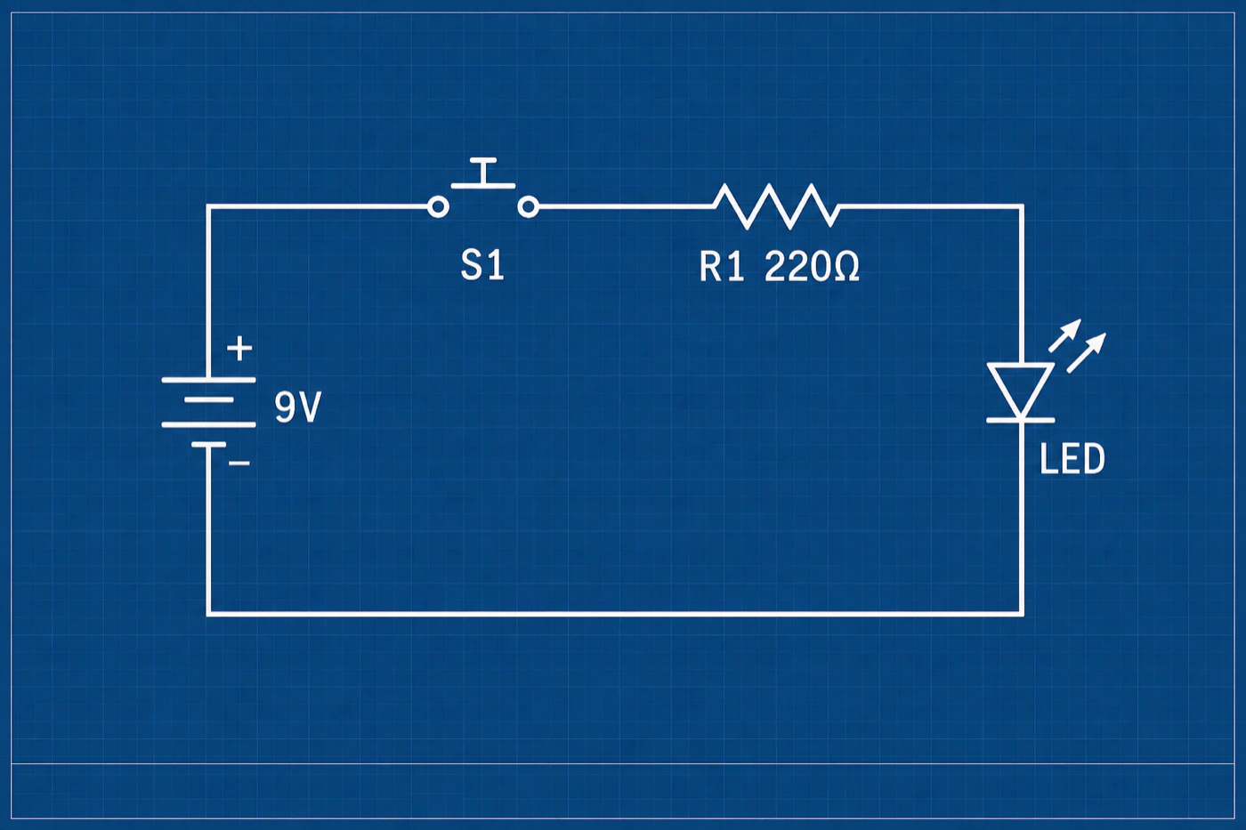
- Find the source. A 9 V battery, with the + and − terminals marked. Every voltage in the circuit is going to be measured against that − terminal.
- Leave from the positive terminal. The line runs to
S1, a push button. It is drawn open, so the circuit is dead until someone presses it. That is information the symbol gives you and the parts list does not. - Next in the path:
R1 220Ω. A resistor in series. Nothing here can branch — there is one line. - Then the LED. It is polarised: the triangle is the anode, the bar is the cathode, and current passes triangle to bar. Wire it backwards and the circuit is dead with nothing to see. The two arrows leaving the symbol are what distinguish it from a plain diode.
- Back to the negative terminal. One unbroken loop, no branches, so this is a series circuit and the same current flows through the button, the resistor and the LED.
That is the diagram read. It is not the diagram checked, and the difference is where the useful work is.
Now check the values against the parts. Take a common 5 mm red LED, the Kingbright WP7113ID. Its datasheet gives a forward voltage of 1.9 V typical at 10 mA, and an absolute maximum DC forward current of 30 mA. The resistor sees whatever the battery does not, so the current through this loop is (9 V − 1.9 V) ÷ 220 Ω, which is about 32 mA — slightly over the absolute maximum for that part. The resistor is dissipating about 0.23 W as well, which a quarter-watt part survives with no margin worth having.
Swap in 470 Ω and the same arithmetic gives about 15 mA and 0.11 W, both comfortably inside the ratings. The 9 V and 220 Ω pairing is the classic textbook combination and it is the one that turns up in generated diagrams, including ours. Reading the diagram tells you it is a series circuit. Only the arithmetic tells you the part is being run past its datasheet.
Four ways to draw the same circuit, and when each is right
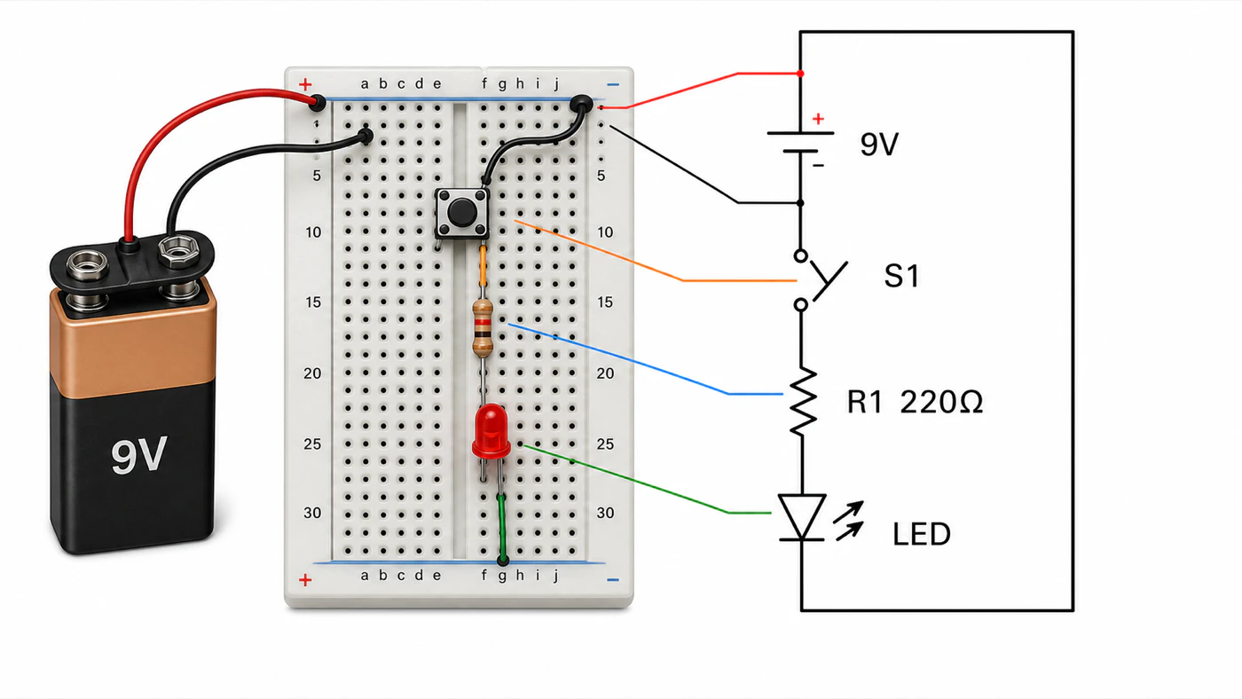
The circuit above has appeared four times in this article in four treatments, which is a fair demonstration of the point: the symbols carry the meaning and the styling carries the audience.
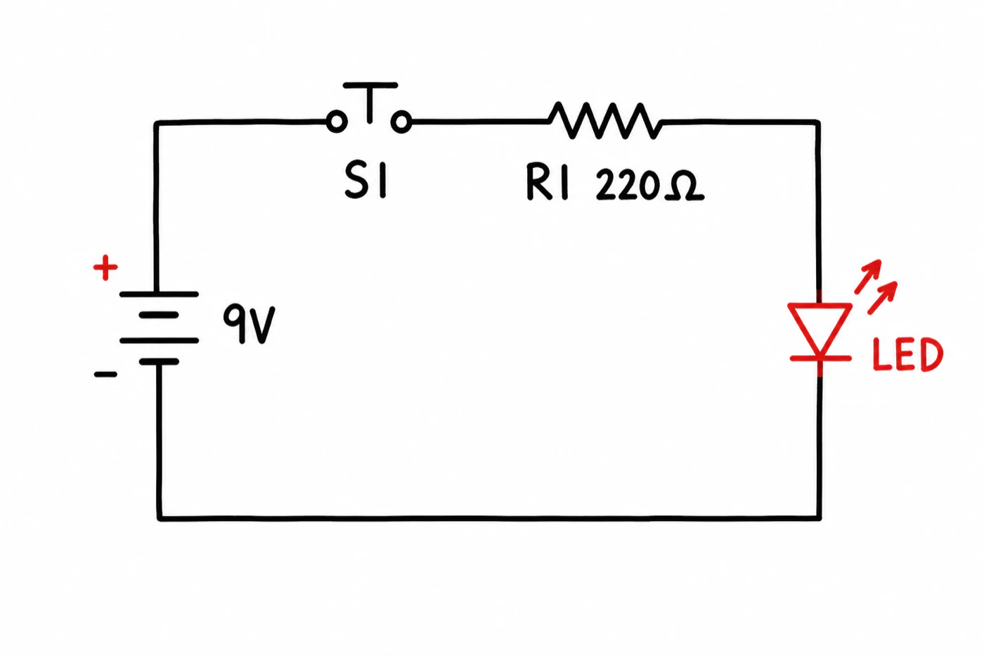
The standard schematic is the default and everything else is a special case. It is what belongs in a paper, a thesis, a datasheet and a lab notebook, because it is the only one of the four that is unambiguous to a reader who was not in the room.
A hand-drawn treatment reads as thinking aloud. That is useful in teaching material, in slides and in a blog post, where a too-finished figure suggests the question is settled. It is the wrong choice for anything a reader might need to build from.
A blueprint treatment is presentation art. It looks good on a cover slide and it costs you a page of ink, a poor greyscale conversion and a reader squinting at a dark background in a printed proceedings. Use it where the figure is decoration, not where it is evidence.
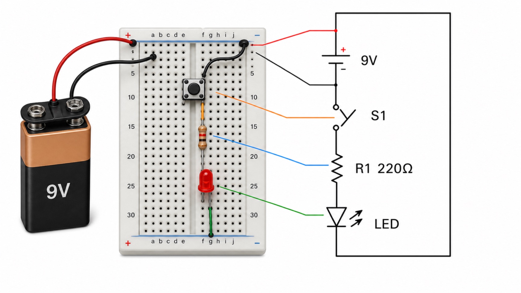
A pictorial or breadboard view is for the person holding the parts. It shows physical placement and hides topology, which is precisely backwards from what a schematic does.
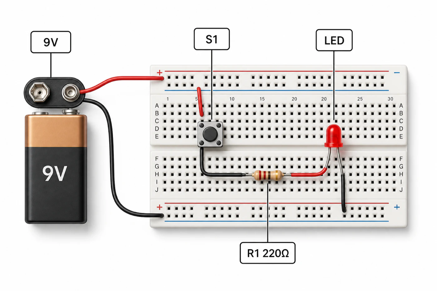
Which is why instructions usually need both, side by side, with leader lines between them — the layout the cover image of this article uses. The schematic answers what is connected to what; the pictorial answers where each part goes. A reader building something for the first time is asking both questions at once.
Drawing a circuit diagram for a paper, thesis or poster
Once a schematic becomes a figure in a manuscript, a second set of rules applies, and they are the journal's rather than the standards body's. IEEE's author guidelines are the natural reference for a circuit figure, and they are specific.
| Requirement | IEEE journal article |
|---|---|
| Preferred format | Vector: PS, EPS or PDF |
| Accepted formats | PS, EPS, PDF, PNG, TIFF. JPEG for author photos only; VSD, GIF and BMP cannot be processed |
| Colour and greyscale raster | Greater than 300 dpi |
| Black-and-white line art | Greater than 600 dpi |
| One column width | 3.5 in / 88.9 mm / 21 picas |
| Two column width | 7.16 in / 182 mm / 43 picas |
| Maximum dimensions | 7.16 × 8.8 in / 182 × 220 mm / 43 × 52 picas |
| Fonts | Helvetica, Times New Roman, Arial, Cambria or Symbol; embedded or converted to outlines |
| Type size | Approximately 9–10 point when viewed at full size |
| File naming | First five letters of the primary author’s surname plus a sequence number, e.g. gonza1.tif |
Three of those rows catch people out on circuit diagrams specifically.
A schematic is line art, so the number is 600 dpi, not 300. The familiar 300 dpi figure is the requirement for photographs and greyscale images. Thin black rules on white are the worst case for rasterisation, and IEEE asks for more than double the resolution for exactly that reason. The better answer is not to rasterise at all: submit vector, and the question stops existing.
Type size is measured at final size, not at the size you drew it. A generated diagram with big comfortable labels becomes a diagram with 4 pt labels the moment it is placed in an 88.9 mm column, because reduction scales the lettering with everything else. Our guide to making scientific figures that survive reduction works through where that goes wrong and how to author for the final width instead.
Check it in greyscale. IEEE's accessibility guidance asks authors to confirm a figure can be interpreted from a greyscale printout, and to use shape as well as colour to carry meaning. On a schematic that usually means the red highlight distinguishing a signal path has to be a dashed line as well as a red one.
If your target journal is not IEEE, the numbers move but the structure does not. Our breakdown of what Scientific Reports and the Nature Portfolio require of a figure covers the most commonly cited alternative, and if the diagram is going on a board rather than into a manuscript, how to make a research poster deals with the different problem of a figure read from two metres away.
One honest limitation. A generated diagram is a raster image, and no amount of resampling turns it into vector. If your journal wants EPS or PDF, treat the generated figure as the draft it is and redraw the accepted version in a vector editor or an EDA package.
Frequently asked questions
How do you read a circuit diagram? Start at the source, follow the line to each symbol in turn, and stop when you are back where you started. No branching means series; a split that rejoins means parallel. Then check the values against the datasheets, because a diagram can be drawn correctly and specified wrongly.
What do the symbols in a circuit diagram mean? Each stands for one component and is defined by a standard — IEC 60617 internationally, IEEE/ANSI 315 in the United States. About a dozen symbols cover almost everything outside a specialist field.
Why is the resistor symbol a rectangle in some diagrams and a zigzag in others? Two standards. The international one draws a rectangle, the American one a zigzag, and they mean the same component. IEC 60617 is maintained continuously and was last released in March 2026; IEEE 315 has not been revised since 1975 and went Inactive-Reserved in November 2019.
What does R1 mean in a circuit diagram? The first resistor on that diagram. The letter is the class, the number is the instance, and the value normally follows.
How can you tell if a circuit is series or parallel from the diagram? Trace from one terminal of the source to the other. If you never had to choose a branch, it is series. If the path splits and rejoins, those branches are parallel.
What do the dots on a circuit diagram mean? A dot means the wires are joined at that point. A crossing without a dot means they are not.
Is a schematic the same as a circuit diagram? Yes, in ordinary use. A wiring diagram is not — it shows physical conductors and terminals, and cares where things are.
What resolution does a circuit diagram need for a journal figure? More than 600 dpi if you must submit a raster, because a schematic is black-and-white line art. Vector is preferred and removes the question.
Where to go next
If you are reading a diagram right now, do the trace first and the arithmetic second. Naming the symbols is the easy half, and the half that never catches an overdriven LED or a capacitor wired backwards.
If you are drawing one for a manuscript, settle the format before the styling: vector if the journal takes it, 600 dpi if it does not, and lettering authored for the column width it will end up in rather than the width you are working at. Making scientific figures that survive reduction is the fuller version of that argument.
If you need a labelled schematic in the next few minutes, the circuit diagram maker will draft one from a sentence in standard symbols, in any of the four treatments shown above. Check the values it gives you against the datasheets before the figure goes anywhere.
Источники
- IEC 60617 — Graphical Symbols for Diagrams (database home) — International Electrotechnical Commissionhttps://library.iec.ch/iec60617Дата обращения: 16 авг. 2026 г.
- IEC 60617:2026 DB — publication record — International Electrotechnical Commissionhttps://webstore.iec.ch/publication/2723Дата обращения: 16 авг. 2026 г.
- IEC TC 3 — Graphical symbols for diagrams — International Electrotechnical Commissionhttps://tc3.iec.ch/tc-activity/graphical-symbols-for-diagrams/Дата обращения: 16 авг. 2026 г.
- IEEE/ANSI 315-1975 — Graphic Symbols for Electrical and Electronics Diagrams (Including Reference Designation Letters) — IEEE Standards Associationhttps://standards.ieee.org/standard/315-1975.htmlДата обращения: 16 авг. 2026 г.
- IEC 81346-2:2019 — Structuring principles and reference designations, Part 2: Classification of objects and codes for classes — International Electrotechnical Commissionhttps://webstore.iec.ch/en/publication/29181Дата обращения: 16 авг. 2026 г.
- IEEE Author Center — Graphics: Resolution and Size — IEEEhttps://journals.ieeeauthorcenter.ieee.org/create-your-ieee-journal-article/create-graphics-for-your-article/resolution-and-size/Дата обращения: 16 авг. 2026 г.
- IEEE Author Center — Graphics: File Formatting — IEEEhttps://journals.ieeeauthorcenter.ieee.org/create-your-ieee-journal-article/create-graphics-for-your-article/file-formatting/Дата обращения: 16 авг. 2026 г.
- IEEE Author Center — Create Graphics for Your Article — IEEEhttps://journals.ieeeauthorcenter.ieee.org/create-your-ieee-journal-article/create-graphics-for-your-article/Дата обращения: 16 авг. 2026 г.
- Kingbright WP7113ID — T-1 3/4 (5mm) Solid State Lamp datasheet — Kingbrighthttps://www.kingbrightusa.com/images/catalog/spec/wp7113id.pdfДата обращения: 16 авг. 2026 г.
Названия журналов, конференций и продуктов являются товарными знаками их правообладателей. Эта страница — независимый редакционный материал, не аффилированный с ними и не одобренный ими. Требования меняются: сверьте каждый пункт с официальными источниками по ссылкам выше перед подачей или печатью.