
Free Body Diagram Maker
Describe the situation and get a physics-correct free body diagram — the body as a dot or a box, every force an arrow drawn from it and labeled W, N, f, T or F_app, with the axes tilted on an incline. Or view the labeled and blank versions below, free.
Or start from an example
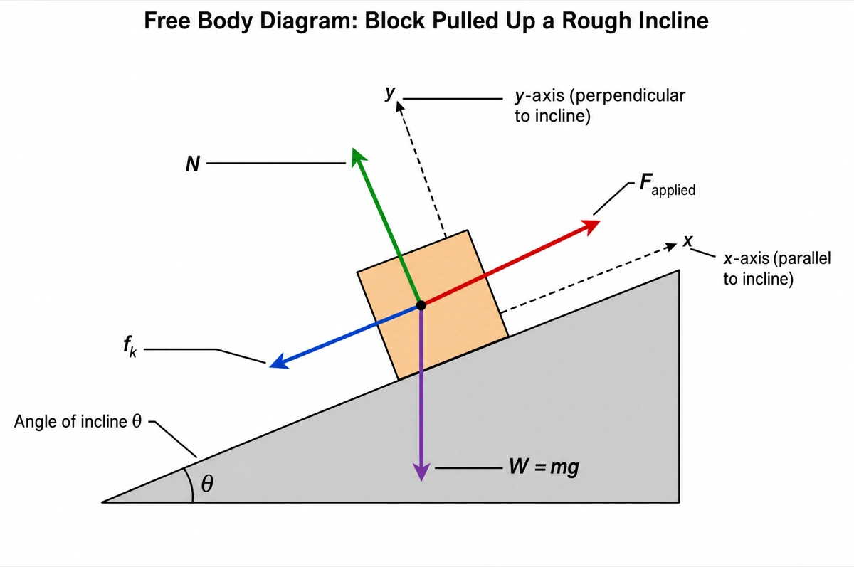
Free body diagram on an incline (answer key)
A block pulled up a rough slope with its weight, normal force, kinetic friction and applied force, and the axes tilted along the incline. Print it as the answer key, or hand it out as a model diagram.
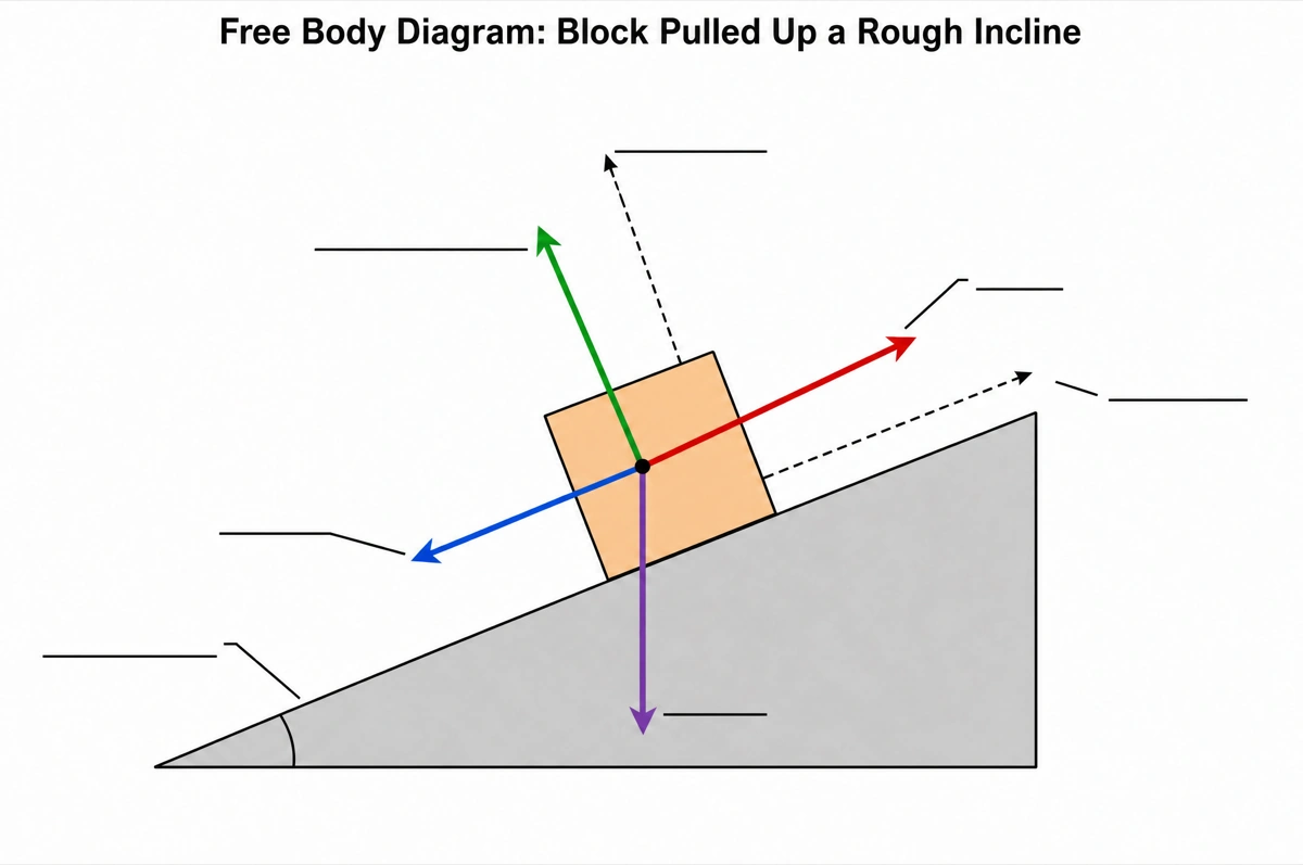
Blank free body diagram to label
The same drawing with an empty answer line where every force symbol was, ready for a worksheet, a quiz or an exam question.
What is a free body diagram?
A free body diagram (FBD) shows one object on its own, drawn as a dot or a simple box, with every external force acting on it drawn as an arrow that starts on the object and points the way the force acts. Each arrow carries its symbol — W or mg for weight, N for the normal force, f for friction, T for tension — and the diagram is the first step in applying Newton's second law.
Key facts
- Only forces belong on it. Velocity, acceleration and the net force are not forces acting on the body, so they are not drawn; the net force is what you work out from the diagram.
- Every force needs something that exerts it. Weight comes from the Earth, the normal force and friction from a surface in contact, tension from a rope or cable. If nothing is pushing or pulling, there is no arrow — which rules out a “centrifugal force” in an ordinary, non-rotating frame.
- The normal force is perpendicular to the surface. On a level floor it points straight up; on an incline at angle θ it tilts with the surface, and with no other force pressing the block into the slope its size is mg cos θ, not mg.
- Friction is parallel to the surface. Kinetic friction points opposite to the direction of sliding; static friction points whichever way stops the object from starting to slip.
- Tilt the axes on an incline. With x along the slope and y perpendicular to it, only the weight has to be split into components: mg sin θ down the slope and mg cos θ into the surface.
How does the free body diagram maker work?
Describe the situation
Name the object, what touches it and how it moves — a crate pushed across a floor, a block sliding down a ramp, a lamp hanging from two cables. Add the angle, the mass or the symbols your course uses if you want them on the drawing.
Pick a style
The default is a clean textbook plate — white background, black arrows, standard symbols. Or apply ink line art, chalkboard, 3D and other finishes.
Refine and export
The result opens in your workspace, where you can move an arrow, rename a symbol on the canvas, upscale and export in high resolution.
Forces on a free body diagram and how to draw each one
The forces that come up most often in mechanics problems, the symbol each is usually given, and the direction its arrow must point. These are the conventions every diagram here follows unless you ask for others.
| Force | Symbol | How to draw it |
|---|---|---|
| Weight (force of gravity) | W or mg (also F_g) | Straight down, toward the center of the Earth, on every object with mass |
| Normal force | N (also F_N) | Perpendicular to the contact surface, pushing away from it |
| Kinetic friction | f_k | Parallel to the surface, opposite to the direction of sliding |
| Static friction | f_s | Parallel to the surface, opposite to the way the object would start to slip |
| Tension | T | Along the rope, string or cable, pulling away from the body |
| Applied force | F_app (also F_a or P) | In the direction of the push or pull |
| Air resistance (drag) | F_air or D | Opposite to the object's velocity through the air |
| Spring force | F_spring | Along the spring, back toward its natural length |
Symbols vary between textbooks. Some courses write F_g and F_N, others W and N, and some write every force as F with a two-letter subscript naming who pushes on whom. Tell the maker which symbols your course uses and only those are drawn.
Free body diagram vs motion diagram: what is the difference?
A free body diagram shows the forces on one object at one instant; a motion diagram shows where the object is at equal time intervals, with its velocity and acceleration arrows. Mixing the two — adding a velocity arrow to a free body diagram — is one of the errors physics teachers mark down most often.
| Free body diagram | Motion diagram | |
|---|---|---|
| What it shows | The forces acting on one object | The object's position at equal time intervals |
| The arrows are | Forces, each exerted by something | Velocity and acceleration |
| The object is drawn | Once, as a dot or a simple box | Several times, as a row of dots |
| Arrow length | In proportion to the size of each force | In proportion to the speed or its change |
| Answers | Why does it move this way? (ΣF = ma) | How does it move? |
| Belongs on it | W, N, f, T, F_app | v and a |
Newton's second law links the two: the net force from the free body diagram points the same way as the acceleration on the motion diagram. If the arrows on your free body diagram cannot add up to the acceleration you expect, a force is missing or pointing the wrong way.
Where are free body diagrams used?
Free body diagrams are used wherever forces have to be added up — physics classes and exams, engineering statics, biomechanics — because Newton's laws can only be applied once every force on one object is drawn. What changes is the object: a dot for a first course, a beam or a joint with forces at their true points of action later on.
School and college physics
Worksheets, lab write-ups and exam answers in high-school physics, AP Physics, IB, A-level and first-year college mechanics, where a free body diagram is usually the first mark in a forces question.
Homework and exam revision
Blocks on inclines, pulleys, elevators and hanging masses — the standard problems, each drawn once correctly so the equations that follow from it are right too.
Engineering statics
Beams, trusses and frames with reaction forces at their supports, drawn where each force acts so moments can be taken about a point.
Biomechanics and sports science
Forces on a limb, a joint or an athlete — muscle forces, joint reactions, ground reaction force — for lectures, reports and papers.
Common questions about free body diagrams
What should a free body diagram include?
The object on its own as a dot or a simple box, one arrow for every external force acting on it, each labeled with its symbol, and a coordinate system. Nothing else — no surroundings, no velocity or acceleration arrows, no net force. That is the default; ask for the incline or the rope to be sketched in and they are.
Can I get a blank free body diagram worksheet?
Yes — view the blank version on this page free, or ask for one and every force label is replaced by an empty answer line. The labeled version is the matching answer key, so the two print as a pair.
How do you draw a free body diagram step by step?
Isolate the object, find every force on it, then draw and label each as an arrow from the body. Start with its weight; add a normal force and friction for every surface it touches and a tension for every rope or cable; add any push or pull. Then choose axes — along and perpendicular to the surface on an incline — and check that every arrow has something exerting it.
Why is the normal force not vertical on an incline?
Because the normal force is always perpendicular to the surface that exerts it — and an incline's surface is tilted. Drawing it straight up is the most common free body diagram mistake. Its size changes too: with no other force pressing the block into the slope, N = mg cos θ, smaller than the weight.
Should I draw a centrifugal force for an object moving in a circle?
No. In the usual inertial frame nothing exerts a centrifugal force, so it has no arrow. The centripetal force is not an extra arrow either: it is the name for the net inward force made up of the forces already drawn — tension on a swinging ball, friction on a car in a bend, gravity on a satellite.
Do velocity and acceleration go on a free body diagram?
No — only forces do. A body moving to the right does not need a force to the right; a crate sliding at constant speed has balanced forces. If you want to show the direction of motion, write it beside the diagram, not as an arrow on it.
Which way does friction point?
Along the surface, opposite to the sliding. Kinetic friction opposes the motion of the object relative to the surface; static friction opposes the way it would start to slip, so on a block resting on a slope it points up the slope.
Where should the force arrows start?
On the object, pointing the way each force acts. In a particle diagram every arrow starts at the dot or the center of the box — even a push is drawn tail on the body. When turning effects matter, as for a beam or a ladder, draw each force at the point where it acts.
Does it calculate the forces, like a free body diagram solver?
It draws the diagram; the equations stay yours. Give it the numbers — the mass, the angle, a coefficient of friction — and they are written on the drawing, but it does not solve for unknown forces, so check any value before you rely on it.
How is this different from a generic AI image tool?
The subject brief is built in. Every render is instructed to follow the standard textbook drawing — each force in its true direction, labeled with its standard symbol — and to leave out anything that is not a force. Check the arrows against your problem before printing; the canvas lets you correct any in place.
Can I use the diagrams for school, teaching or publication?
Yes — diagrams you generate are yours to use in worksheets, presentations, lab reports, theses and papers. Export high-resolution raster up to 4K depending on the model.
Can I change the labels after generating?
Yes. The result opens in a canvas workspace that recognizes the diagram labels — you can rename a symbol, translate the text, move an arrow's label, redraw a region or recolor without regenerating the whole figure.
Keep exploring
Our other diagram tools, and the guides behind them.

Draw your free body diagram
From a one-line description of the problem to a labeled, printable diagram in about a minute.
Start drawing