
The five ANSI/SLAS microplate standards fix the outside of a 96-well plate to a hundredth of a millimetre and say almost nothing about the wells. This is every dimension they specify, every number they leave to the manufacturer, and where three suppliers disagree on the same nominally standard plate.
What is the 96-well plate format?
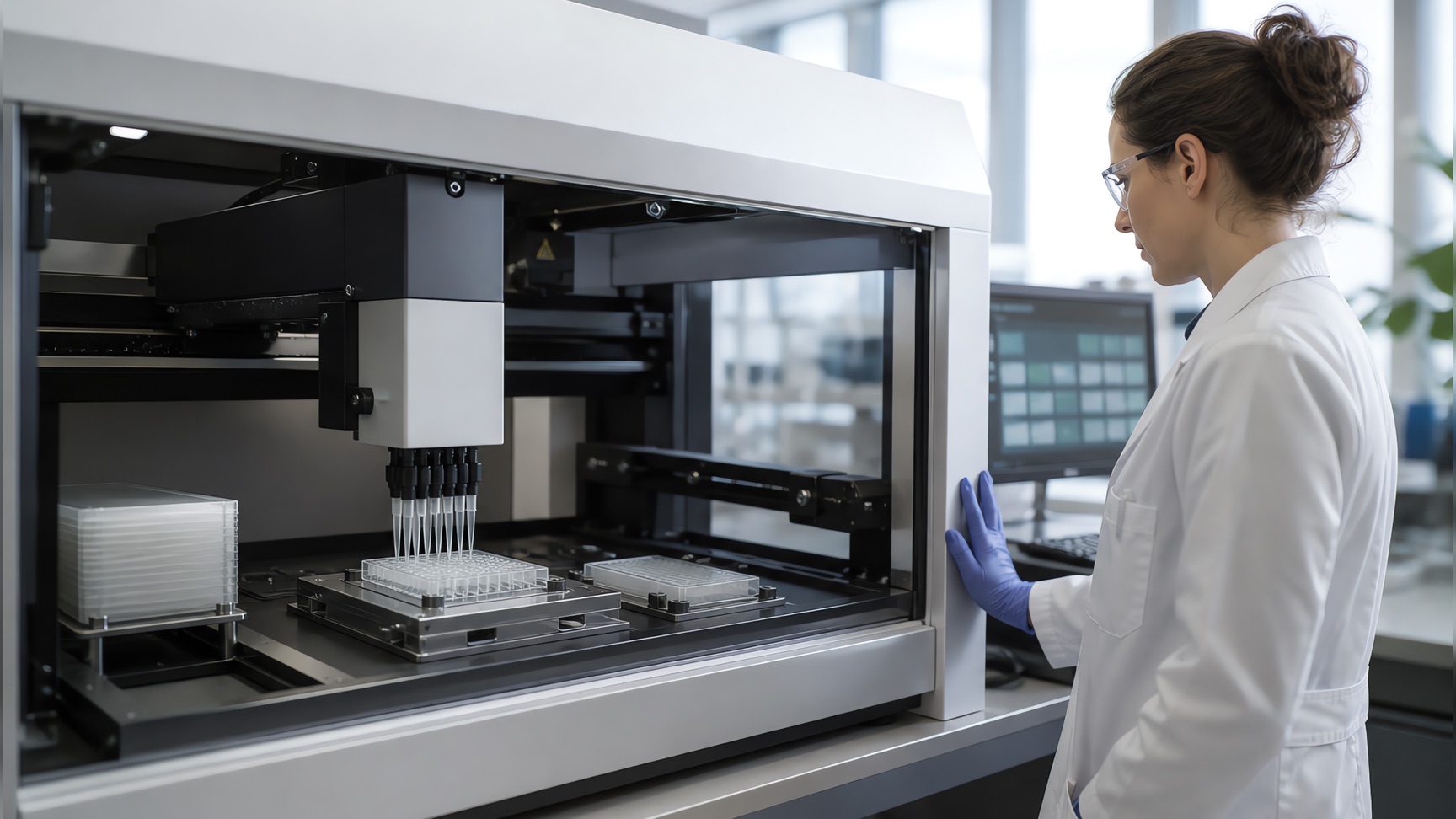
A 96-well plate is a tray of eight rows by twelve columns of wells, moulded to an outside geometry that every reader, washer, sealer and liquid handler in the building already expects. Thermo Fisher lists the array on its Nunc MicroWell plate as 8 × 12.
That geometry is not a convention that settled by accident. It is a set of American National Standards maintained by the SLAS Microplate Standards Advisory Committee, whose membership ANSI requires to be a balanced representation of microplate manufacturers, manufacturers of instruments that use microplates, industrial and academic users, and members with a general interest. Five standards are currently in force, reaffirmed by the committee in June 2017.
| Standard | Covers |
|---|---|
| ANSI/SLAS 1-2004 (R2012) | Footprint dimensions |
| ANSI/SLAS 2-2004 (R2012) | Height dimensions |
| ANSI/SLAS 3-2004 (R2012) | Bottom outside flange dimensions |
| ANSI/SLAS 4-2004 (R2012) | Well positions |
| ANSI/SLAS 6-2012 | Well bottom elevation |
The numbering skips 5. All four of the 2004 standards were formerly issued as ANSI/SBS, which is the designation still printed in many supplier catalogues and reproduced in a great deal of older documentation.
Read the list again and the shape of the thing becomes clear. Footprint, height, flange, well position, well bottom elevation. Every one of those describes the outside of the plate or where the wells are, and none of them describes what a well is. That distinction runs through the rest of this page, because it is the difference between a number you can hold a supplier to and a number that happens to be true of the plate on your bench.
96-well plate dimensions: footprint, height and flange
| Dimension | Value | Source |
|---|---|---|
| Footprint length | 127.76 mm (5.0299 in) | ANSI/SLAS 1-2004 |
| Footprint width | 85.48 mm (3.3654 in) | ANSI/SLAS 1-2004 |
| Corner radii | 4 × R 3.18 ± 1.6 mm (.1252 ± .0630 in) | ANSI/SLAS 1-2004 |
| Footprint tolerance | ± 0.5 mm overall; ± 0.25 mm at zones B-G, C-F, D-J, E-H | ANSI/SLAS 1-2004 |
| Typical height | 14.35 mm (0.56560 in), ± 0.76 mm overall, ± 0.25 mm within area “K” | ANSI/SLAS 2-2004 |
| Minimum external clearance | 1 mm (0.0394 in), in the area of the wells only | ANSI/SLAS 2-2004 |
| Short flange height | 2.41 ± 0.38 mm (0.0948 ± 0.0150 in) | ANSI/SLAS 3-2004 |
| Medium flange height | 6.10 ± 0.38 mm (0.2402 ± 0.0150 in) | ANSI/SLAS 3-2004 |
| Tall flange height | 7.62 ± 0.38 mm (0.3000 ± 0.0150 in) | ANSI/SLAS 3-2004 |
| Maximum bottom projection | 6.85 mm (.2697 in) | ANSI/SLAS 3-2004 |
Three conditions travel with those numbers and are quoted less often than they should be.
They apply at 20 °C. ANSI/SLAS 1-2004 states that unless otherwise specified all dimensions are applicable at 20 degrees C (68 degrees F), and that compensation may be made for measurements made at other temperatures. Polystyrene moves enough with temperature that a plate measured straight out of a 37 °C incubator is not the plate the standard describes.
They exclude draft. Every one of the standards carries the same note: dimensions and tolerances do not include draft. Injection-moulded walls taper, and that taper sits outside the tolerance rather than inside it.
The footprint has to be continuous. ANSI/SLAS 1-2004 requires the footprint to be continuous and uninterrupted around the base of the plate, which is what lets a gripper pick the plate from any side.
The flange heights are a menu rather than a single value. A plate may carry the short 2.41 mm flange, the medium 6.10 mm, the tall 7.62 mm, a short flange with interruptions, or two different heights at once: 2.41 mm on the short sides and 7.62 mm on the long sides. Where a single height is used it must be the same on all four sides. This is the dimension most likely to be the reason a plate that measures correctly still will not seat in a particular stacker.
Where the wells sit: the A1 offset and the 9 mm pitch
ANSI/SLAS 4-2004 fixes two offsets and one interval, and everything else about the grid follows from them. The centre of well A1 sits 14.38 mm from the short-side datum and 11.24 mm from the long-side datum. Well centres are 9 mm apart. A positional tolerance of ⌀0.70 mm applies to all 96 wells.
The arithmetic closes on itself, which is a useful check when drawing a plate or writing code that addresses one. Twelve columns give eleven intervals, so the grid spans 11 × 9 = 99 mm; 14.38 + 99 + 14.38 = 127.76, the footprint length. Eight rows give seven intervals, so 7 × 9 = 63 mm; 11.24 + 63 + 11.24 = 85.48, the footprint width. The well array is centred on the plate, and the offsets are what centre it.
The 9 mm pitch is also why the plate formats nest. ANSI/SLAS 2-2004 tabulates pitch by format, and each step halves the previous one.
| Number of wells | Pitch P | Half pitch Q |
|---|---|---|
| 96 | 9 mm (.3543 in) | 4.5 mm (.1772 in) |
| 384 | 4.5 mm (.1772 in) | 2.25 mm (.0886 in) |
| 1536 | 2.25 mm (.0886 in) | 1.125 mm (.0443 in) |
A 384-well plate carries its wells at half the 96-well pitch, which is what lets a 96-channel head address one quadrant of a 384-well plate without any mechanical change. The halving is the whole reason the higher-density formats were specified that way.
ANSI/SLAS 4-2004 also carries a requirement that is easy to overlook because it is about marking rather than geometry: the top left well of the plate shall be clearly marked, for example on the left with the letter “A” or the numeral “1”, or at the top with the numeral “1”. Additional markings may be provided. The alphanumeric coding moulded into most plates is a manufacturer’s extension of that minimum.
How much does a 96-well plate hold?
Here the standards stop, and the question has no single answer. Not one of the five specifies well volume.
| Plate | Well bottom | Total well volume | Recommended working volume |
|---|---|---|---|
| Corning 3596 | Flat | 360 µL | 75–200 µL |
| Corning 3788 | Round | 330 µL | 75–200 µL |
| Thermo Scientific Nunc 167008 | Flat | 400 µL | Not stated |
| Greiner CELLSTAR 655180 | Flat, chimney well | Not stated | 25–340 µL |
Total well volume across those four runs from 330 µL to 400 µL, a spread of roughly 20%, and all four are standard-format 96-well plates. Two of them come from the same supplier and differ by 30 µL for no reason other than the shape of the well bottom.
Working volume is the number to design an experiment around, and it is narrower than the total for reasons that have nothing to do with the plate: meniscus, surface tension, the clearance a dispensing tip needs, and the risk of cross-contamination when a plate is moved on a deck. Corning recommends 75 to 200 µL for both its flat-bottom and round-bottom plates, and separately gives 100 to 200 µL as the recommended medium volume for the TC-treated 3596. Greiner gives a wider 25 to 340 µL for the CELLSTAR 655180, whose chimney-well construction separates neighbouring wells more completely than a shared top surface does.
The practical consequence: a protocol that says “fill each well to 300 µL” is portable across none of these plates without checking. On the Corning 3788 it exceeds the total volume of the well.
Well surface area, and why it is not 0.32 cm² everywhere
Growth area per well is the other number readers arrive looking for, and it is also the manufacturer’s rather than the standard’s.
| Plate | Growth area per well | Source |
|---|---|---|
| Corning 3596, flat bottom, TC-treated | 0.32 cm² (approx.) | Corning |
| Greiner CELLSTAR 655180, flat bottom, TC | 34 mm² = 0.34 cm² | Greiner Bio-One |
The two differ by about 6%. For most purposes that is noise. For anything normalised per unit area it is not: seeding density in cells per cm², protein yield per cm², a specific activity reported per unit of growth area. A figure carried between two labs running nominally identical plates inherits that 6% silently, and Corning’s own listing hedges its number with “approx.”, which is a fair warning rather than a hedge to ignore.
Note also what the round-bottom plate does not have. Corning lists a growth area for the TC-treated flat-bottom 3596 and none for the untreated round-bottom 3788, which is consistent: growth area is a property of a surface intended for adherent culture, not a geometric fact about a well.
Reading a plate map: A1 to H12
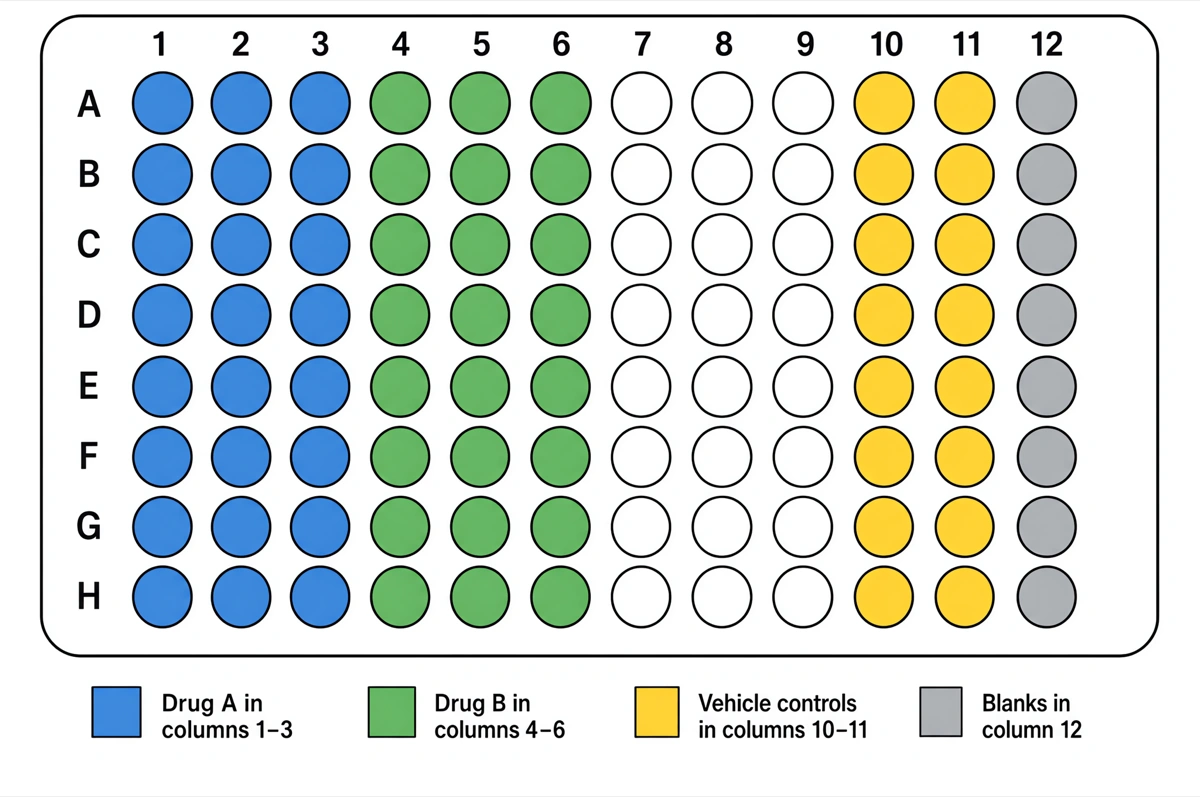
Rows run A to H from top to bottom, columns 1 to 12 from left to right, and a well identifier is the row letter followed by the column number. A1 is the top left well, H12 the bottom right. That is the whole convention, and the only part of it the standards require is that the top left well be clearly marked.
Two consequences follow from the fact that the rest is convention rather than specification.
Orientation is carried by the plate, not by the map. A plate rotated 180° in a carrier still has its A1 corner marked, and the marking is the only thing that tells a reader or an operator which corner it is. A plate map drawn without an explicit A1 marker is ambiguous in exactly the way the standard set out to prevent.
Traversal order is a local choice. Reading down the columns (A1, B1, C1 …) and reading along the rows (A1, A2, A3 …) are both common, instrument software disagrees on which it exports, and neither is more correct. It is worth stating which one a dataset uses, because the difference silently transposes an 8 × 12 grid.
What the standards deliberately leave open
ANSI/SLAS 6-2012 is the standard that makes the omission explicit, and it is worth reading carefully because its title suggests it fixes more than it does. It applies to microplates with flat well bottoms and it defines a vocabulary: well bottom elevation, well bottom elevation variation, intra-well bottom elevation variation, well bottom width, well depth, bottom thickness. Its stated purpose is to describe the definitions and to outline the conditions required for making the necessary measurements.
That is a measurement standard. On well bottom width it says the dimension is measured to the theoretical sharp corner and is reported as a nominal value. Defining how a dimension is to be reported is not the same as requiring it to take a particular value, and nothing in the five standards requires one.
| Fixed by ANSI/SLAS | Left to the manufacturer |
|---|---|
| Footprint 127.76 × 85.48 mm | Well volume |
| Corner radii 3.18 mm | Well diameter and well depth |
| Plate height 14.35 mm | Well bottom shape: flat, round, V or chimney |
| Flange height 2.41 / 6.10 / 7.62 mm | Growth area per well |
| Well pitch 9 mm | Surface treatment and plate colour |
| A1 centre at 14.38 / 11.24 mm | Optical properties and bottom thickness |
| Marking of the top left well | Skirt style beyond the flange requirement |
Suppliers are precise about this when read closely. Greiner Bio-One states that its CELLSTAR microplates have a uniform footprint which conforms to the recommendation of the American National Standards Institute, and names ANSI/SBS 1-2004 specifically. That is a claim about the footprint standard, and it is exactly the claim the standard supports. The growth area of 34 mm² and the 25 to 340 µL working volume on the same page are Greiner’s own figures, offered as product specifications rather than as conformance to anything.
The rule that falls out of this, for a methods section or a figure legend: cite the catalogue number, not the format. “A 96-well plate” identifies the footprint and the well positions. It does not identify the volume, the growth area, the well shape or the surface, and those are usually the properties a reader would need in order to repeat the work.
Drawing a 96-well plate that matches the standard
Draw it at 1:1 in millimetres and the specification becomes the drawing rather than something the drawing approximates. The outline is a 127.76 by 85.48 rectangle with 3.18 mm corner radii. Well A1 goes at 14.38, 11.24. Every other well is that point plus a multiple of 9 in each direction. The figure at the top of this page is built from exactly those numbers and nothing else.
Four errors show up often enough in published plate figures to be worth naming.
The grid transposed. Twelve columns across and eight rows down. A plate drawn 12 rows by 8 columns is a different object, and it happens most often when a figure is built from a spreadsheet whose orientation was never checked.
A1 in the wrong corner. Top left. If a figure is drawn from a photograph of a plate on a bench, the plate may well have been rotated.
Wells distributed edge to edge. Spacing the wells evenly across the full width, rather than insetting the first centre by 14.38 mm and stepping by 9 mm, produces a plate that looks right and matches nothing. The two offsets are what make the array centred.
A well diameter presented as a specification. Any plate figure has to draw wells at some size. Stating which plate was drawn, or labelling the diameter as nominal, is the honest version. The figure above takes the second route.
For a figure that carries measurements, vector output is what preserves them. Our guide to making scientific figures for publication covers the resolution, line weight and type size that survive reduction to a single journal column, and the same rules apply to a plate schematic as to a plot.
Frequently asked questions
What are the dimensions of a 96-well plate? 127.76 mm × 85.48 mm with four corner radii of 3.18 ± 1.6 mm, from ANSI/SLAS 1-2004, and a typical height of 14.35 mm ± 0.76 mm from ANSI/SLAS 2-2004. A tolerance of ± 0.5 mm applies overall, tightening to ± 0.25 mm at the datum zones, and the dimensions apply at 20 °C.
What is the well spacing on a 96-well plate? 9 mm between well centres in both directions. ANSI/SLAS 2-2004 tabulates 9 mm for 96 wells, 4.5 mm for 384 and 2.25 mm for 1536, each half the previous one.
Where is well A1? Top left, with its centre 14.38 mm from the short-side datum and 11.24 mm from the long-side datum, to a positional tolerance of ⌀0.70 mm. ANSI/SLAS 4-2004 requires the top left well to be clearly marked.
How much liquid does a well hold? That depends on the plate, because no standard specifies it. Corning gives 360 µL for the flat-bottom 3596 and 330 µL for the round-bottom 3788; Thermo Fisher gives 400 µL for the flat-bottom Nunc 167008. Recommended working volumes are 75 to 200 µL for the Corning plates and 25 to 340 µL for the Greiner CELLSTAR 655180.
What is the growth area of one well? 0.32 cm² approximately at Corning for the 3596, and 34 mm² at Greiner Bio-One for the 655180. Both are manufacturer specifications, not standardised values, and the roughly 6% difference propagates into anything reported per unit area.
Is well volume standardised at all? No. ANSI/SLAS 6-2012 defines well depth, bottom thickness and well bottom width as measurement terms and says well bottom width is reported as a nominal value. It defines how to report those dimensions; it does not fix them.
How many rows and columns are there? Eight rows lettered A to H, twelve columns numbered 1 to 12. Thermo Fisher lists the array as 8 × 12.
Where to go next
For the drawing rules that decide whether a plate schematic survives the journey to print, see making scientific figures for publication.
If the plate figure is headed for a graphical abstract, the size and format constraints are set by the journal rather than by the plate: graphical abstract requirements covers what the major publishers ask for.
If it is headed for a poster instead, how to make a research poster covers the board sizes and the type sizes that stay readable at two metres.
References
- ANSI/SLAS 1-2004 (R2012) — Footprint Dimensions for Microplates — Society for Laboratory Automation and Screeninghttps://www.slas.org/SLAS/assets/File/public/standards/ANSI_SLAS_1-2004_FootprintDimensions.pdfAccessed Aug 29, 2026
- ANSI/SLAS 2-2004 (R2012) — Height Dimensions for Microplates — Society for Laboratory Automation and Screeninghttps://www.slas.org/SLAS/assets/File/public/standards/ANSI_SLAS_2-2004_HeightDimensions.pdfAccessed Aug 29, 2026
- ANSI/SLAS 3-2004 (R2012) — Bottom Outside Flange Dimensions for Microplates — Society for Laboratory Automation and Screeninghttps://www.slas.org/SLAS/assets/File/public/standards/ANSI_SLAS_3-2004_BottomOutsideFlangeDimensions.pdfAccessed Aug 29, 2026
- ANSI/SLAS 4-2004 (R2012) — Well Positions for Microplates — Society for Laboratory Automation and Screeninghttps://www.slas.org/SLAS/assets/File/public/standards/ANSI_SLAS_4-2004_WellPositions.pdfAccessed Aug 29, 2026
- ANSI/SLAS 6-2012 — Well Bottom Elevation — Society for Laboratory Automation and Screeninghttps://www.slas.org/SLAS/assets/File/public/standards/ASNI_SLAS_6-WellBottomElevation.pdfAccessed Aug 29, 2026
- ANSI/SLAS Microplate Standards — Society for Laboratory Automation and Screeninghttps://www.slas.org/education/ansi-slas-microplate-standards/Accessed Aug 29, 2026
- Corning 3596 — 96-well Clear Flat Bottom Polystyrene TC-treated Microplate — Corning Incorporatedhttps://ecatalog.corning.com/life-sciences/b2c/US/en/Microplates/Assay-Microplates/96-Well-Microplates/Corning%C2%AE-96-well-Clear-Flat-Bottom-Polystyrene-TC-treated-Microplates/p/3596Accessed Aug 29, 2026
- Corning 3788 — 96-well Clear Round Bottom Polystyrene Not Treated Microplate — Corning Incorporatedhttps://ecatalog.corning.com/life-sciences/b2c/US/en/Microplates/Assay-Microplates/96-Well-Microplates/Corning%C2%AE-96-well-Clear-Round-Bottom-Polystyrene-Microplates/p/3788Accessed Aug 29, 2026
- Nunc MicroWell 96-Well, Nunclon Delta-Treated, Flat-Bottom Microplate (167008) — Thermo Fisher Scientifichttps://www.thermofisher.com/order/catalog/product/167008Accessed Aug 29, 2026
- CELLSTAR Cell Culture Microplate, 96 well, PS, F-bottom (chimney well), 655180 — Greiner Bio-Onehttps://shop.gbo.com/en/usa/products/bioscience/cell-culture-products/cellstar-cell-culture-microplates/96-well-cell-culture-microplates/655180.htmlAccessed Aug 29, 2026
Journal, conference and product names are the trademarks of their respective owners. This page is independent editorial content and is not affiliated with, authorised by, or endorsed by them. Specifications change — confirm every requirement against the official sources linked above before you submit or print.