
Circuit Diagram Maker
Describe your circuit in plain words — the AI works out the components and draws a clean, correctly wired diagram. Schematic, breadboard view, or both side by side.
Circuit diagram examples
Five ways to draw the same circuit, each shown with a real render — click a card to apply the style, or zoom for the full image.
What is a circuit diagram?
A circuit diagram (also called a schematic, electrical diagram or electronic schematic) is a graphical representation of an electrical circuit. It shows every component as a standardized symbol and every connection as a line, so anyone who reads schematics can understand — and rebuild — the circuit at a glance. It differs from a wiring diagram, which shows the physical arrangement of parts and cables, and from a pictorial diagram, which draws components as they actually look on a breadboard or PCB.
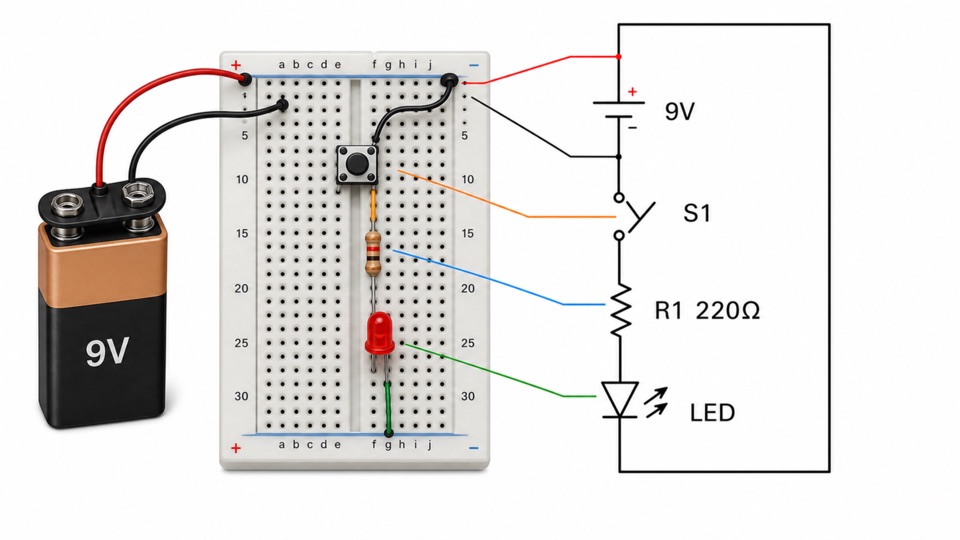
This circuit diagram maker produces all three views. Describe what the circuit should do in plain words and the AI works out the component list — with sensible values like the right current-limiting resistor — then draws it as a textbook schematic with standard symbols, a realistic breadboard build, or both panels side by side, ready for a lesson handout, a lab report, a tutorial or a paper.
Key facts
- A circuit diagram shows electrical connection, not physical position — two components drawn next to each other may sit at opposite ends of the board.
- Two symbol conventions are both current: ANSI/IEEE zigzag resistors, common in US textbooks, and IEC 60617 rectangular ones, common in Europe.
- A junction dot means the crossing wires are connected; crossing lines without a dot are not connected.
- In a series circuit the current is the same everywhere and the voltages add; in a parallel circuit the voltage is the same across each branch and the currents add.
- A wiring diagram answers a different question from a schematic: it shows where the cables physically run, not how the circuit works.
How does the circuit diagram maker work?
Describe the circuit
Write what the circuit should do in plain words — "a 9V battery lights an LED through a push button". Component values are optional: the AI fills in sensible ones, like the right current-limiting resistor.
Pick a diagram style
A clean textbook schematic with standard symbols, a realistic breadboard build, both panels side by side, a whiteboard sketch, or a classic blueprint.
Refine in the workspace
The diagram opens in your workspace where you can edit regions, adjust labels, upscale and export in high resolution for handouts, slides or papers.
Standard circuit diagram symbols
Schematics are readable everywhere because they share a symbol vocabulary. These are the symbols you will meet in almost every circuit diagram — and the ones the generator draws, with correct polarity where it matters:
Battery
Long plate is the positive terminal, short plate the negative.
Resistor
Limits current; value written beside it, e.g. 220Ω.
Capacitor
Two parallel plates; stores charge, value in µF or nF.
Polarized capacitor
Electrolytic type — the curved plate must go to negative.
Diode
Current flows only in the arrow direction, into the bar.
LED
A diode that emits light — the small arrows point away.
Switch (SPST)
Open lever between contacts; closes to complete the circuit.
Push button
Momentary switch — closes only while pressed.
Ground
Common reference point; all ground symbols are connected.
Lamp
Incandescent bulb — a circle with a cross inside.
Inductor
A coil; stores energy in a magnetic field, value in mH.
Transistor (NPN)
Amplifies or switches — arrow on the emitter points out.
Resistor and capacitor symbols come in two conventions — the zigzag and curved-plate forms shown here (ANSI/IEEE, common in US textbooks) and rectangular boxes and straight plates (IEC, common in Europe). Both are correct; pick one convention per figure and stay consistent.
Where are circuit diagrams used?
Lessons, worksheets and lab reports
Clean schematics for physics lessons, worksheets and lab reports — describe the circuit from the textbook and get a diagram ready to print, with the whiteboard style for a hand-drawn look.
Build guides and electronics tutorials
The breadboard view and the build + schematic pair explain an Arduino or Raspberry Pi hookup at a glance — the exact figure style electronics tutorials and course slides need.
Papers, theses & textbooks
Publication-quality figures with exact labels and consistent typography for methods sections, theses and teaching material — no drawing software or symbol libraries to learn.
Circuit symbols chart: ANSI and IEC conventions
The same component is drawn two ways depending on which standard a textbook follows. Both are correct — pick one per figure and stay consistent.
| Component | ANSI / IEEE (common in US textbooks) | IEC 60617 (common in Europe) |
|---|---|---|
| Resistor | Zigzag line | Plain rectangle |
| Variable resistor | Zigzag with a diagonal arrow through it | Rectangle with a diagonal arrow through it |
| Capacitor | One straight and one curved plate | Two straight parallel plates |
| Inductor | Series of loops | Filled or outlined rectangle |
| Cell | Long plate positive, short plate negative | Long plate positive, short plate negative |
| Lamp | Circle with a cross inside | Circle with a cross inside |
| Switch | Hinged line breaking the wire | Hinged line breaking the wire |
| Fuse | Rectangle with a line through it, or an S-curve | Rectangle with a line through it |
| Earth / ground | Three descending horizontal bars | Three descending horizontal bars |
Only the passive components differ between the two standards. Cells, lamps, switches and ground are drawn the same way in both, which is why a mixed figure often goes unnoticed — and still reads as sloppy to anyone who works in one convention.
Series vs parallel circuits
In a series circuit there is one path, so the current is identical at every point and the supply voltage divides between the components. In a parallel circuit each branch sees the full supply voltage and the branch currents add up to the total. That single difference determines every other contrast below, including what happens when one component fails.
| Series circuit | Parallel circuit | |
|---|---|---|
| Number of paths | One | One per branch |
| Current | The same at every point | Divides between branches, and the branch currents add |
| Voltage | Divides between components | The same across every branch |
| Total resistance | Sum of the resistances | Always smaller than the smallest branch |
| Adding a component | Raises total resistance, lowers current | Lowers total resistance, raises total current |
| If one component fails open | The whole circuit stops | The other branches keep working |
| Typical use | Switches and fuses in a supply line | Household lighting and sockets |
| Drawn as | One loop, components end to end | A ladder, branches between two rails |
For resistors, the total is R₁ + R₂ + … in series and 1/R = 1/R₁ + 1/R₂ + … in parallel — which is why two equal resistors in parallel give exactly half the resistance of one.
Common questions about circuit diagrams
How does the AI circuit diagram generator work?
You describe the circuit in plain language. The AI first works out the component list — designators, values and the order they connect in — then draws the diagram with standard circuit symbols and your exact labels. If your description is brief, it engineers the standard working version of that circuit for you.
Can it draw a breadboard diagram for Arduino-style projects?
Yes. The Breadboard build style draws the circuit as a realistic pictorial build — battery, jumper wires, resistors with color bands, ICs on the board — and the Build + schematic style pairs that picture with the matching symbol schematic in one figure, which is ideal for tutorials and classroom handouts.
Does it use standard circuit symbols?
The schematic styles use conventional textbook symbols — battery plates, zigzag resistors, diode triangles, switch contacts — with correct polarity on batteries, diodes and electrolytic capacitors, drawn with clean right-angle wiring.
Is this an EDA tool? Can I export a netlist or simulate the circuit?
No — this makes diagram *figures* for teaching, publications, slides and articles, not editable netlists for fabrication. If you need SPICE simulation or PCB layout, use an EDA package; if you need a beautiful, correct-looking diagram in seconds, this is the faster path.
Can I make electrical wiring diagrams or logic circuit diagrams too?
Yes — describe any circuit: household wiring runs, relay logic, logic-gate networks, sensor hookups or power supplies. The AI lays out whatever components you describe; dedicated diagram types for wiring and logic are on the roadmap.
Is the circuit diagram maker free? Can I use the diagrams commercially?
You can generate diagrams on the free plan (with a watermark on exports). Paid plans remove the watermark and unlock every model and high-resolution export, and you can use your diagrams in courses, publications and commercial material.
How do you read a circuit diagram?
Follow the current from one terminal of the supply back to the other, and treat every line as a perfect wire. Junction dots mark where wires connect; lines that cross without a dot do not. Positions on the page mean nothing — the diagram states connection only, so a component drawn near the battery may be physically anywhere. Read component values written beside each symbol, and check the supply polarity before working out direction.
What is the difference between a series and a parallel circuit?
A series circuit has one path, so the same current flows everywhere and the supply voltage divides between components. A parallel circuit has one path per branch, so every branch sees the full supply voltage and the branch currents add. The practical consequence: break one component in a series circuit and everything stops, while in a parallel circuit the other branches keep working.
Why do resistor symbols look different in different textbooks?
Because two standards are both in current use. The zigzag resistor and curved-plate capacitor come from the ANSI/IEEE convention common in US textbooks; the plain rectangle and two straight plates come from IEC 60617, common in Europe and in international standards. Neither is more correct. Ask for whichever convention your course or journal uses and the whole figure is drawn in it.
How do you draw a circuit diagram?
Lay the supply on one side, run the components along the path between its terminals, and keep wires as straight horizontal and vertical lines with right-angle corners. Use a junction dot wherever wires connect and leave crossings undotted. Write values beside their symbols. Here, describing the circuit in a sentence does all of that — including keeping polarity correct on cells, diodes and electrolytic capacitors.
What is the difference between a schematic, a wiring diagram and a pictorial diagram?
A schematic shows how the circuit works: standard symbols, connection only, no physical layout. A wiring diagram shows where the cables actually run between real terminals, which is what you need for installation or fault-finding. A pictorial diagram draws components as they look on a breadboard or a board. All three can describe the same circuit and none substitutes for another.
Can it draw logic circuit symbols?
Yes — AND, OR, NOT, NAND, NOR and XOR gates are drawn in either the distinctive-shape form used in most US textbooks or the rectangular IEC form, along with inputs, outputs and inversion bubbles. Say which convention you want; if you do not, the distinctive-shape form is used, since it is the more widely recognised of the two.
What does the earth or ground symbol mean?
It marks the reference point that all voltages in the circuit are measured against, usually 0 V. Several ground symbols on one diagram do not mean several separate points — they are all the same node, drawn repeatedly so the figure does not fill with long return wires. Chassis ground and earth ground are distinct symbols and are not interchangeable in mains work.
Sources
- IEC 60617 — Graphical symbols for diagrams — International Electrotechnical Commission
- Resistors in Series and Parallel — College Physics 2e, section 21.1 — OpenStax
Keep exploring
Our other diagram tools, and the guides behind them.
Tools

Draw your first circuit diagram
From plain-language description to publication-ready diagram in about a minute.
Start drawing